
Part 4: Display drivers and setup
Different ways to access a TFT display on a Raspberry
HDMI or mini-HDMI display port
The display setup was a bit more intricate to get up and running. In Linux, there are several ways to control a TFT display attached to a Raspberry Pi. First, there is the standard HDMI port on the Raspberry Pi, or the mini-HDMI port on the Raspberry Pi Zero 2W. This method is rather straightforward and displays the system default interface on the screen without the need for setup or drivers. It’s probably the most convenient way to visualize your OS, software, applications, and data. These displays are the actual “framebuffer” devices and under Linux are visible and accessible in the /dev tree as /dev/fb0, /dev/fb1, and so on. The default Raspberry Pi /boot/config.txt limits this to a maximum of 2 framebuffer devices.
TFT displays, SPI bus connected with own driver
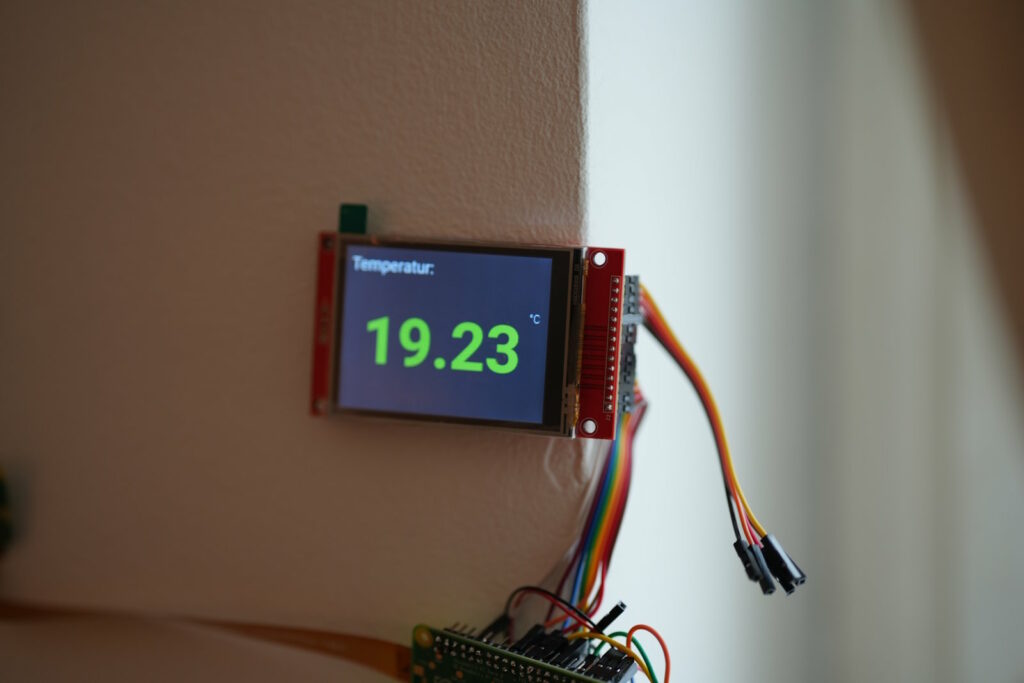
Then there is the SPI bus on the Raspberry Pi, which is accessible via the soldered 40-pin GPIO header. These displays can be accessed with their own driver code and are capable of performing functions implemented by the driver code. If a function is defined, you can make use of it. The main functions here are mostly something like displaying images, writing text, drawing lines, polygons, and circles, along with operational ones like initializing the display, setting the backlight brightness, or clearing the display.
This approach is fully functional, and my temperature terminals do not actually need more. However, you have to write your own code to display the collected values from the database on the tiny TFT display. I will cover this part later in this guide when connecting the ST7789V 2-inch TFT display, as I had difficulties operating this specific one in framebuffer mode—it was mirrored, and that was hardcoded into the st7789v driver itself. Rewriting the driver would have been too much work 🙂
In general, these displays will not show a console or a graphical desktop environment. Additionally, there is also framebuffer copy code, but that is way too complicated for this guide.
TFT display connected to the SPI bus as framebuffer devices with overlay files in the /boot/config.txt
With the ILI9341 display, I initially intended to use the framebuffer approach because I couldn’t manage to use the ST7789V display as a framebuffer device, and the tiny TFTs are the only displays on the temperature terminals. You’ll find numerous ILI9341 display overlay or connection instructions on the internet. Unfortunately, none of them worked well for me, and it took me quite a while until I found a GitHub entry with a link to an overlay file that I successfully used. I also followed the wiring instructions on that page, as all those ports were still available and not occupied by my other sensors on the GPIO header.
2.8inch SPI Module ILI9341 SKU:MSP2807
Link to the rusconi GitHub site here: https://github.com/rusconi/Raspberry-Pi-TFT-FB1-HowTo
Be aware that the MISO pin is not mentioned in this description, but connecting the MISO pin of the TFT panel to RPi physical pin 21 – GPIO 11 worked for me.
Read the full display wiring here: https://www.wetransco.de/rapsberry-zero-2w-bme68x-ds18b20-ili9341-tft-hardware-setup/
The actual LCD-show.git with the overlay file for the ili9341 can be downloaded here and installed like this:
git clone https://github.com/goodtft/LCD-show.git
cd LCD-show/
sudo cp ./usr/tft9341-overlay.dtb /boot/overlays/tft9341.dtbo
You have to update your /boot/config.txt file to load the tft9341.dtbo overlay file at bootup:
sudo nano /boot/config.txtAnd add these lines at the end:
dtparam=spi=on

dtoverlay=tft9341:rotate=270
gpio=13=op,dh
After you saved your /boot/config.txt with CTRL-O, CTRL-X, reboot your Raspberry and you should be able to see a framebuffer device in your /dev folder:
ls /dev/fb*If you add these two lines at the end of the line in /boot/cmdline.txt:
fbcon=map:10 fbcon=font:VGA8x8
You can also see the console login after a reboot that shows up on your display.
You now can configure a screen in the X11 system with editing your config:
nano /etc/X11/xorg.conf.d/99-fbdev.conf
Copy and paste the following lines and save the file again:
Section "Device"
Identifier "FBDEV"
Driver "fbdev"
Option "fbdev" "/dev/fb1"
EndSection
Section "Screen"
Identifier "Default Screen"
Device "FBDEV"
EndSection
From there you can also start a graphical Desktop environment by logging in and typing:
FRAMEBUFFER=/dev/fb1 startx