
Part 2: hardware list, setup and wiring
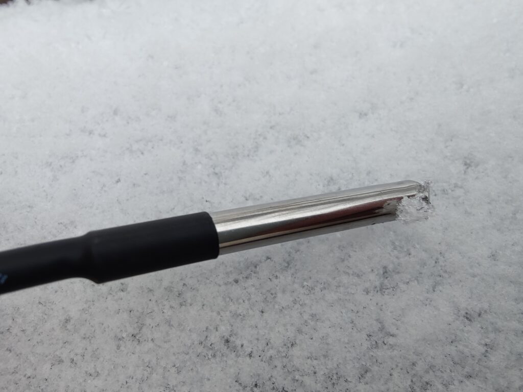
I’m commencing this brief tutorial with my Raspberry Pi Zero 2W featuring the ili9341 2.8-inch TFT screen, as it’s one of the most widely used displays available. I’ve incorporated a Waveshare BME68x sensor for inside temperature, air pressure, and humidity readings, complemented by an external DS18B20 sensor with an extension cable housed in a waterproof casing.
Here are the hardware components I acquired for this project:
- Raspberry Pi Zero 2 W (or any larger model would suffice)
Amazon alternative - GPIO Header (this needs to be soldered on!)
- SD card for the operating system
- BME68x sensor (inside temperature, air pressure, humidity)
- DS18B20 and TO-92 (outside temperature)
- 2.8″ ILI9341 240×320 TFT LCD Display (I haven’t utilized the touch controller yet)
Optional components:
- Coolers (optional but good for durability, especially in summer)
- Cooling Fan (also optional)
1. Start by soldering on the GPIO header for convenient plugging and replugging of all sensors. Note that there are plans to sell Raspberry Pi Zero 2 WH (with an added H for header) that come pre-equipped with a GPIO header, eliminating the need for soldering. However, I couldn’t find those, so I opted for this model without a header. This should give you the following wiring plan:
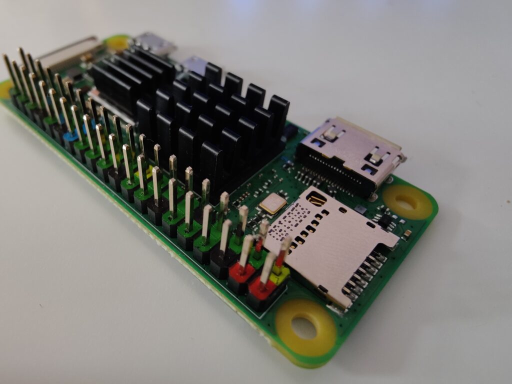
2. Optionally equip your Raspberry Pi Zero 2W with a cooler, especially if it might be exposed to direct sunlight, needs to endure summer months, or has a considerable workload depending on other services running on it. With only temperature readouts, screen image views, and database services, my Raspberry stays quite cool, ranging between 30 and 35 degrees Celsius. However, one of my Raspberries also has a webcam (camera module 3) since I plan to use it as a UVC webcam. When the video streaming service is active, it easily reaches the 65-degree range quickly. You can also use the video streaming service as a webcam outside your cabin or holiday home, depending on where you place the climate control system.
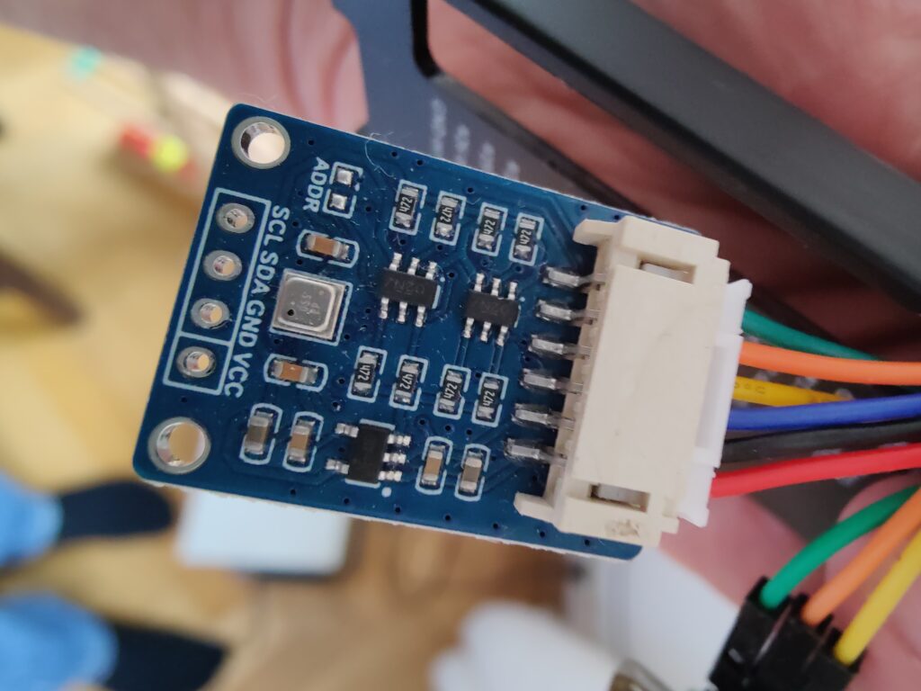
3. Connect the Bosch BME68x sensor to it. I use a BME680 and a BME688 on the two Raspberries, although this doesn’t make any difference for this project. The 688 version includes optional AI support, but that requires additional proprietary code from Bosch, which I haven’t installed on my setup yet. My code works the same for either the BME680 or the BME688 variant.
Official Rapsberry Pi Zero 2W Pinout and hardware documentation
BME68x wiring:
- In I2C mode:
| VCC | 3.3/5 Volts | physical pin 1 (red cable) |
| GND | Ground | physical pin 6 (black cable) |
| SDA | SDA1 | physical pin 4 (blue cable) |
| SCL | SCK | physical pin 5 (yellow cable) |
The ADDR/MISO and CS connectors are not used in this setup. Avoid touching the sensor during installation, as the components are sensitive and may provide inaccurate values if not treated carefully.
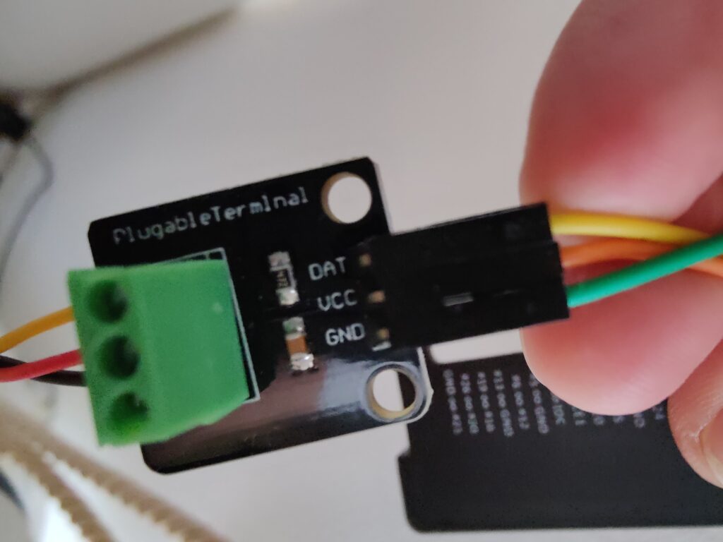
4. Connect the DS18B20 outside temperature sensor using the 1-wire bus system of the Raspberry. This sensor only uses one data line into the Raspberry, so it only has three cables, as you also need VCC (power 3.3 or 5 Volts) and GND (grounding).
DS18B20 wiring:
| VCC | 3.3/5 Volts | physical pin 2 (orange cable) |
| GND | Ground | physical pin 9 (green cable) |
| DQ Pin | Data | physical pin 18 (GPIO 24) (yellow cable) |
5. Connect the 2.8-inch ILI9341 display to the Raspberry’s GPIO header. Since I opted not to run in text mode and used generated pictures for presentation, I set up the display as the default system display capable of running a graphical desktop manager—a so-called framebuffer device. This is a different setup that I’ll describe in another tutorial with my Raspberry Pi Zero 2 that has the ST7789V controlled display. Using a framebuffer display eliminates the need for additional drivers or code to display images in a slideshow on the screen. It’s quite easy to use the “fbi” program (framebuffer image viewer) on Linux to generate a slideshow here. A small drawback: fbi doesn’t allow some cool fade-in or fade-out effects for the slideshow, which I have on the other Raspberries. I’ll still attempt to create the fade effect using the display PWM dimming to black, but that is a later project not covered here.
Let’s wire the screen:
| Display | RPi Pin | GPIO |
| VCC | 17 | 3.3 Volt |
| GND | 6 | GND |
| CS | 24 | 8 |
| RESET | 13 | 27 |
| DC | 15 | 22 |
| SDI/MOSI | 19 | 10 |
| SCK | 23 | 11 |
| LED | 33 | 13 |
| MISO | 21 | 9 |
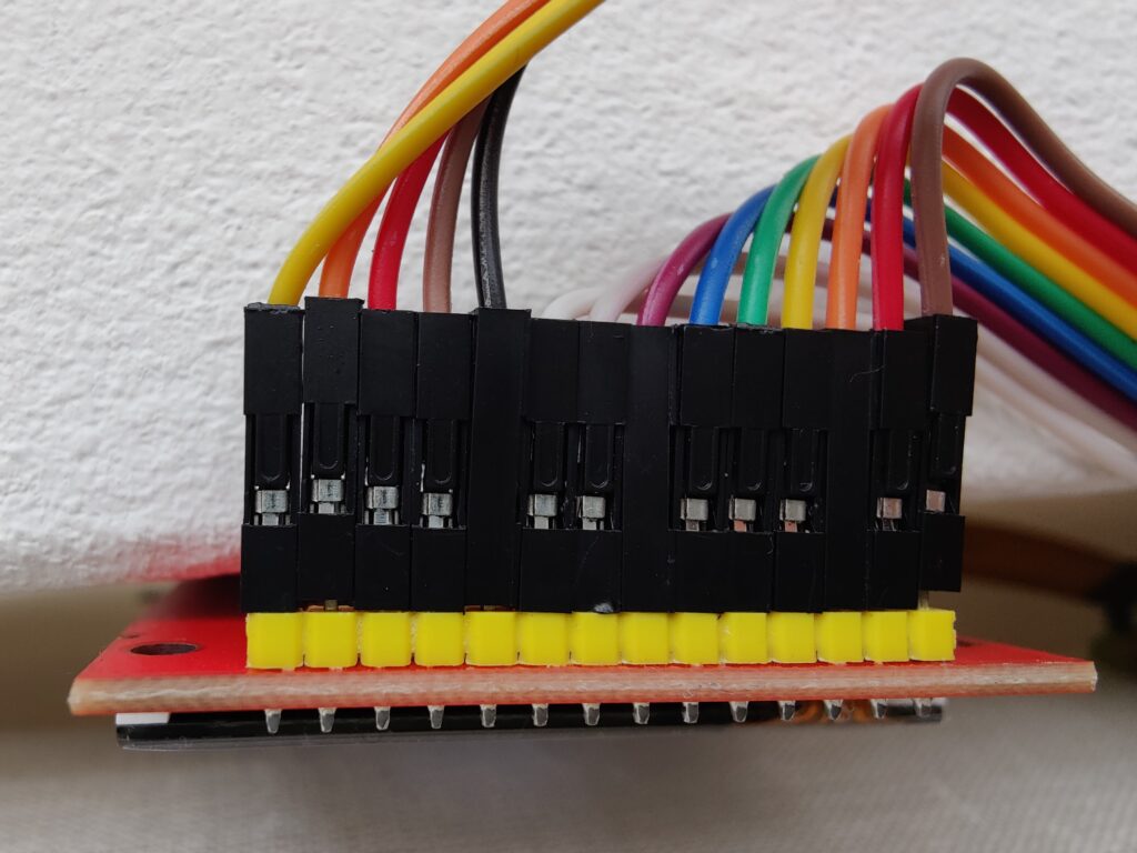
With all these accessoires, the Raspberry GPIO header is quite filled already. Now, the hardware is set up and ready to be activated by software. Continue to the next part that covers Operating System installation, hardware and driver configuration, and software for our climate project.